
1LHX - Quick Start Guide Installation
(Single-Phase Input)
QUICKSTART 1LHX, Revision 001
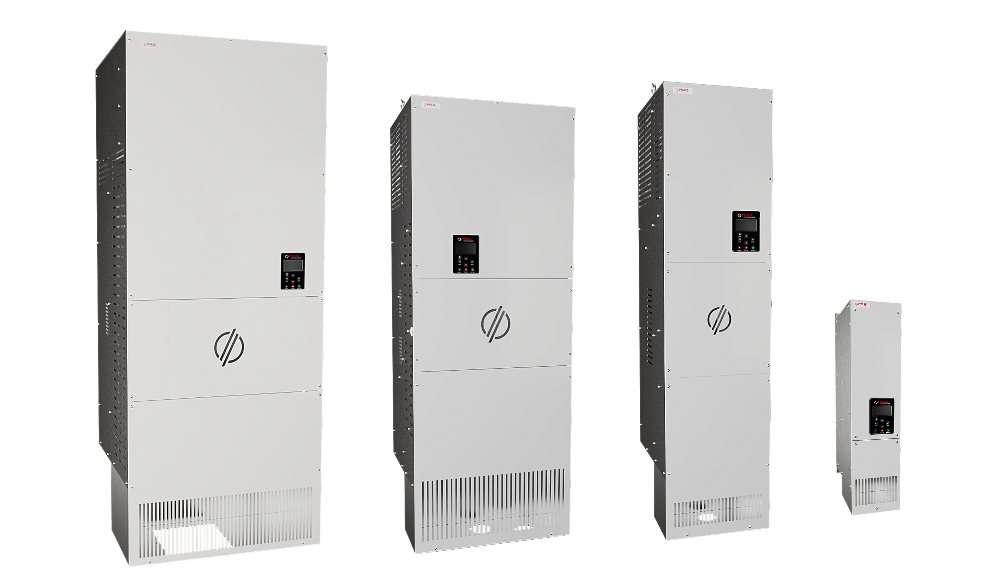
Mounting the VFD
-
Mount the enclosure using provided brackets in such a way that it is fully supported.
Note: 16” (400mm) clearance above, 12” (300mm) below, and 3” (35mm) around required for ventilation. Less clearance may be required for smaller frames. See manual for details.
Connect Wiring
- Remove screws necessary to remove cover.
-
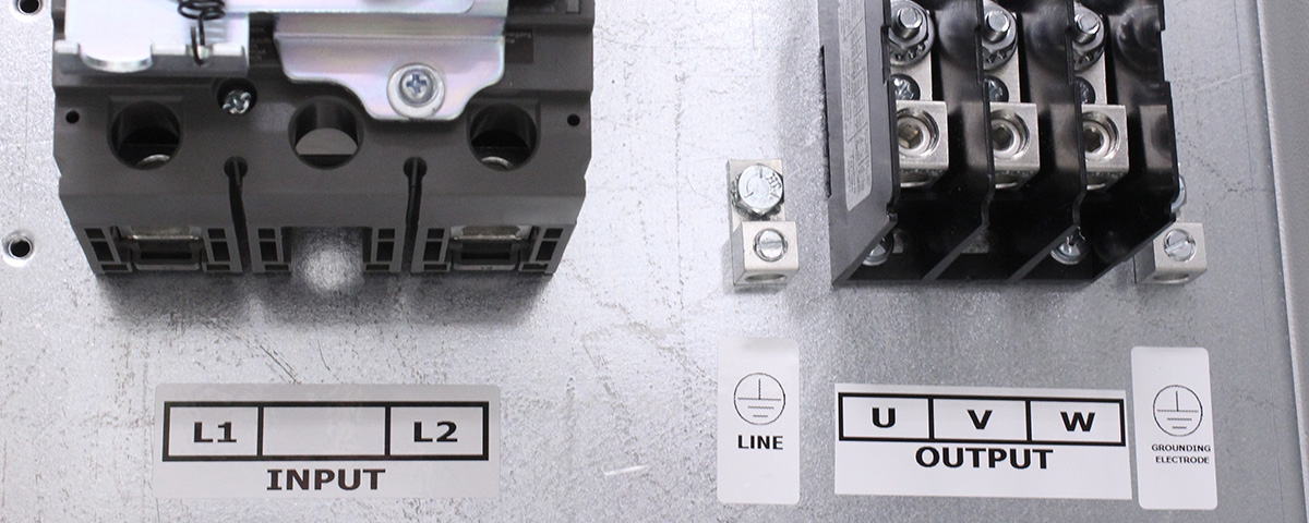
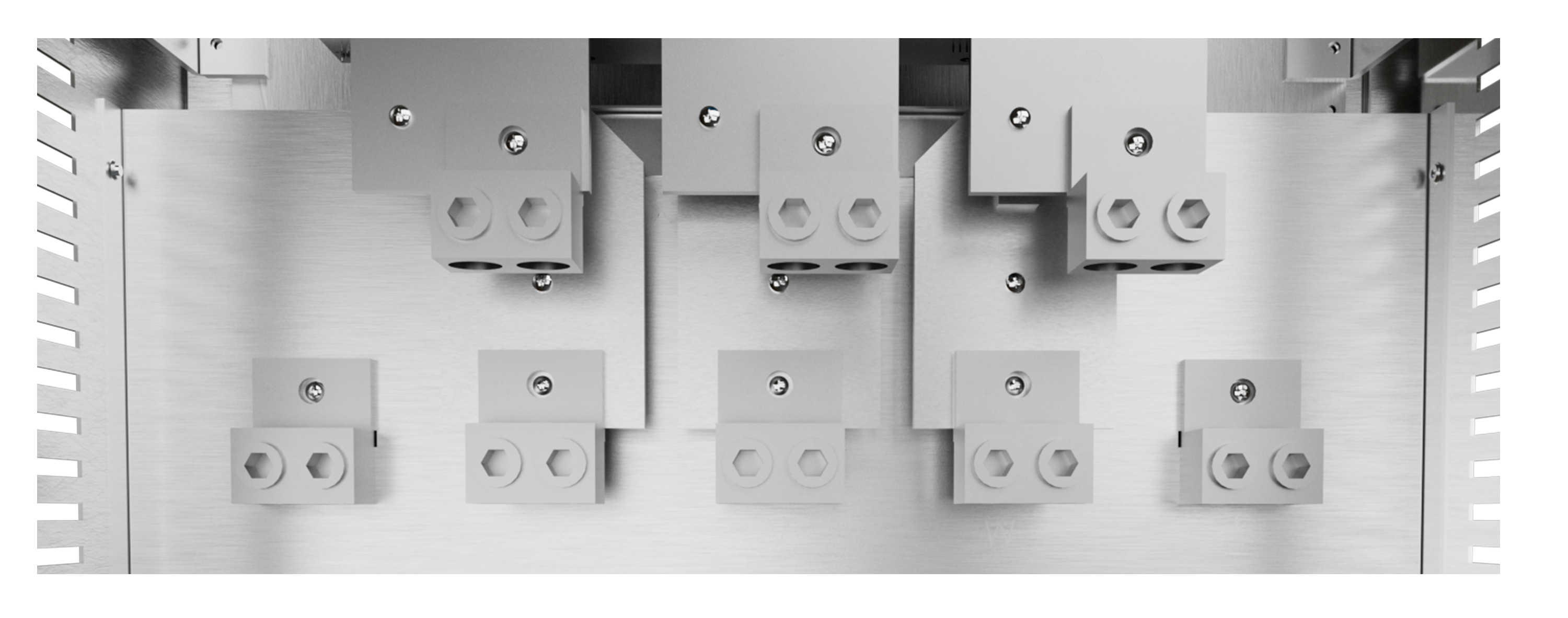
Secure the appropriate ground wires into the lugs marked with the ground symbol.
Note: 4 ohms or less to earth ground recommended. - Connect motor leads to terminal block labeled output. (U, V, W)
- Connect power leads to terminals labeled input. (L1, L2)
 ground symbol
-
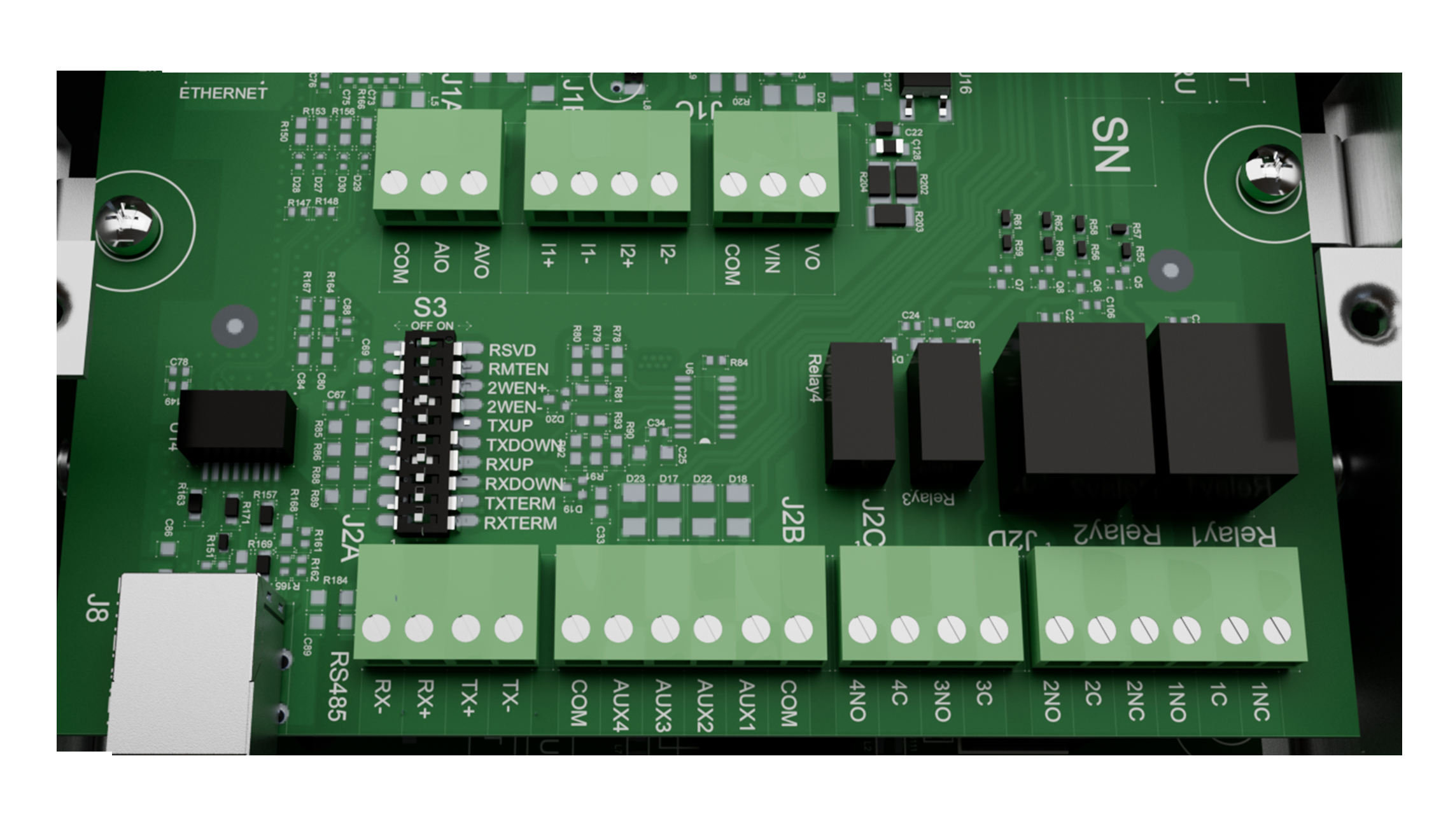
If using transducer, install into a 1/4” NPT non-metallic fitting and run the wire back to the VFD.
Note: Cut transducer leads to length. DO NOT coil extra wire or connect shielding ground wire. DO NOT run transducer leads next to motor leads. Only cross at 90 degrees. - Install the Black wire into the l1 - terminal and the remaining White or Red wire into the l1+ terminal on the control board.
Powering up the VFD
- Replace the cover and reinstall previously removed screws.
-
To bypass initial setup, press the HOME button, or use the Perfect
Pressure Wizard by choosing YES (ENTER) when prompted.
Note: Hold the BACK and ENTER buttons for 3 seconds to reset to default configuration.
Optional: To add a run/stop from a PLC, float switch, or similar, remove
the orange jumper wire and make those connections to AUX2 and COM.
Caution: No voltage may be introduced on these terminals.
Download
LHX Series Manual
phasetechnologies.com/support/lhx
LHX Series Manual
