
1LH - Quick Start Guide Installation
(Single-Phase Input)
QUICKSTART 1LH, Revision 002
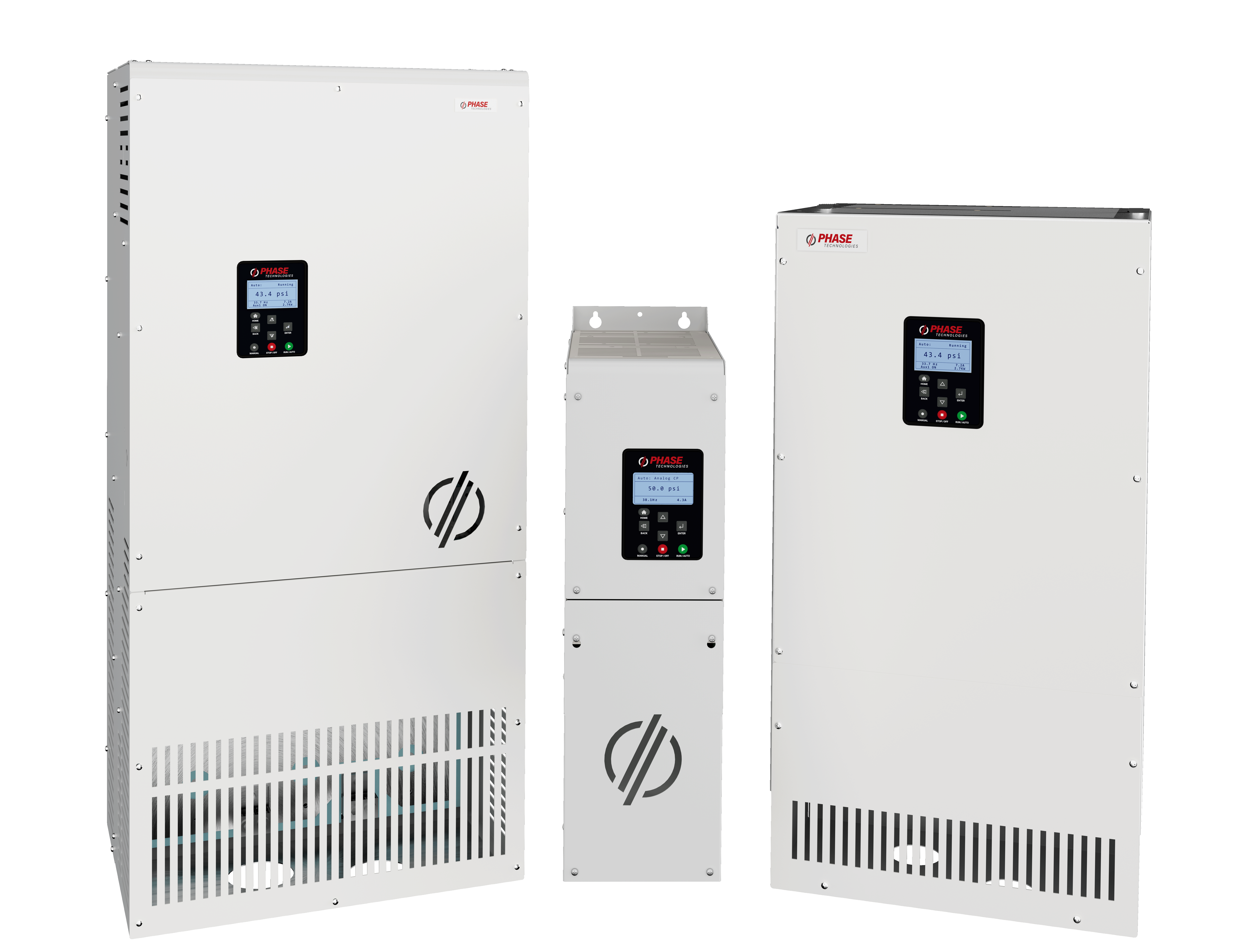
Mounting the VFD
- Mount the enclosure using provided brackets in such a way that it is fully supported.
Note:16” (400mm) clearance above, 12” (300mm) below, and 3” (35mm) around required for ventilation. Less clearance maybe required for smaller frames. See manual for details.
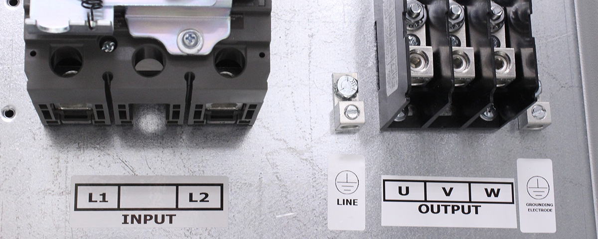
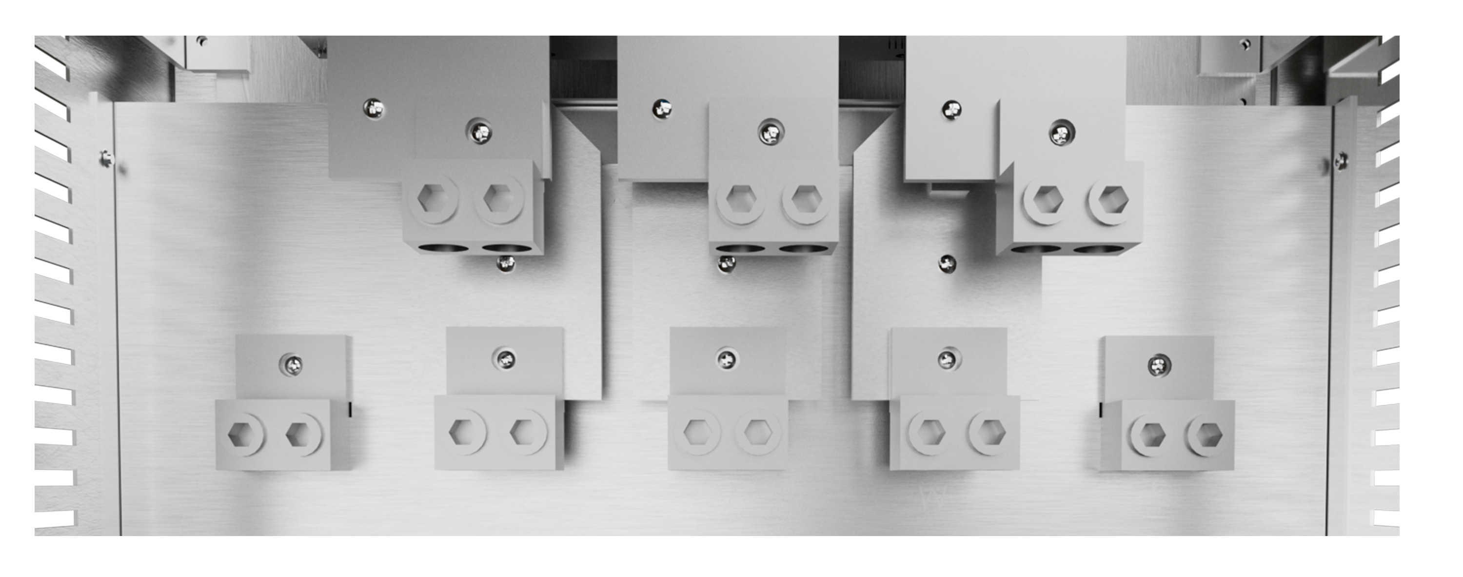
Connect Wiring
- Remove screws necessary to remove cover.
- Secure the appropriate ground wires into the lugs marked with the ground symbol.
Note: 4ohms or less to earth ground recommended - Connect motor leads to terminal block labeled output. (U, V, W)
- Connect power leads to terminals labeled input. (L1, L2)
 ground symbol
-
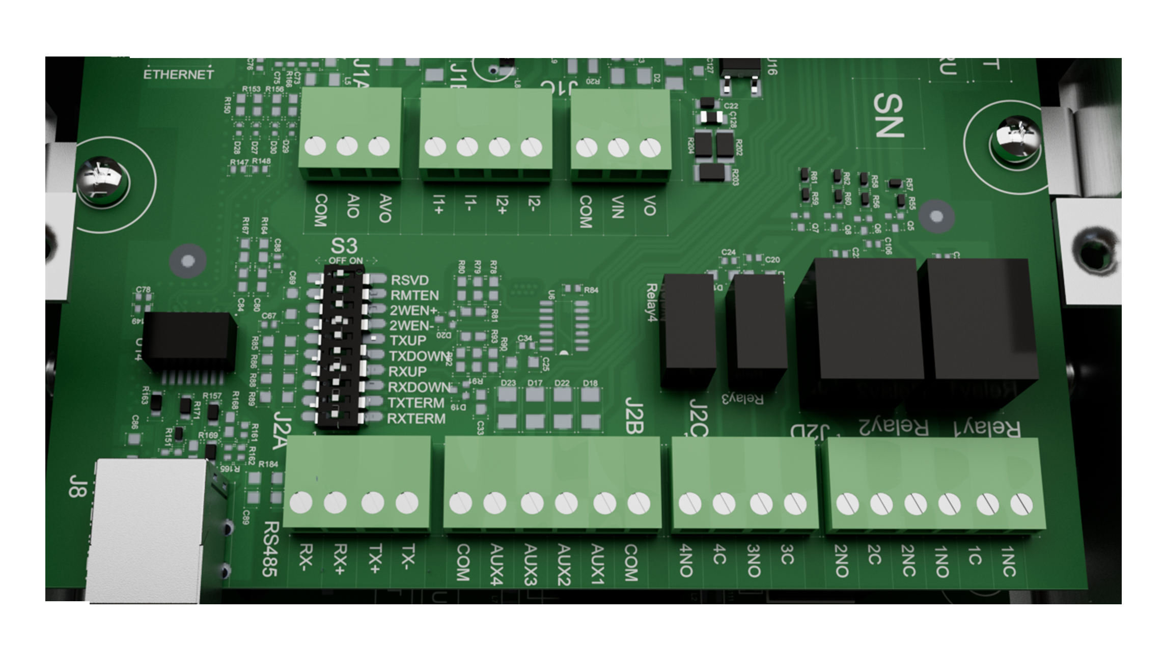
If using transducer, install into a 1/4” NPT non-metallic fitting and run the wire back to the VFD, up to the terminal area and cut to length.
Note: Cut transducer leads to length, DO NOT coil extra wire or connect shielding ground wire. DO NOT run transducer leads next to motor leads. If necessary, only cross transducer and motor leads at a 90 degree angle.
- Install the Black wire into the l1 - terminal and the remaining White or Red wire into the l1+ terminal on the control board.
Powering up the VFD
- Replace the cover and reinstall previously removed screws.
- To bypass initial setup, press the HOME button, or, to use the Perfect Pressure Wizard, choose YES (ENTER) when prompted.
Note: Hold the BACK and ENTER buttons for 3 seconds to reset the VFD to default configuration
Optional: To add a run/stop from a PLC, float switch, or similar, remove the orange jumper wire and make those connections to AUX2 and COM.
Caution: No voltage may be introduced on these terminals.
Download
LH Series Manual
phasetechnologies.com/support/lh
LH Series Manual
