Motor Protection

What are Motor Protection Filters?
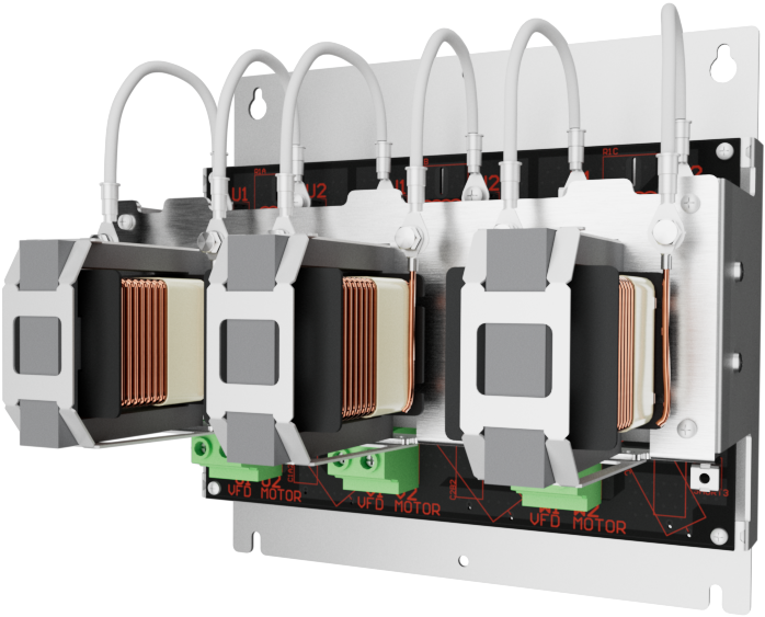
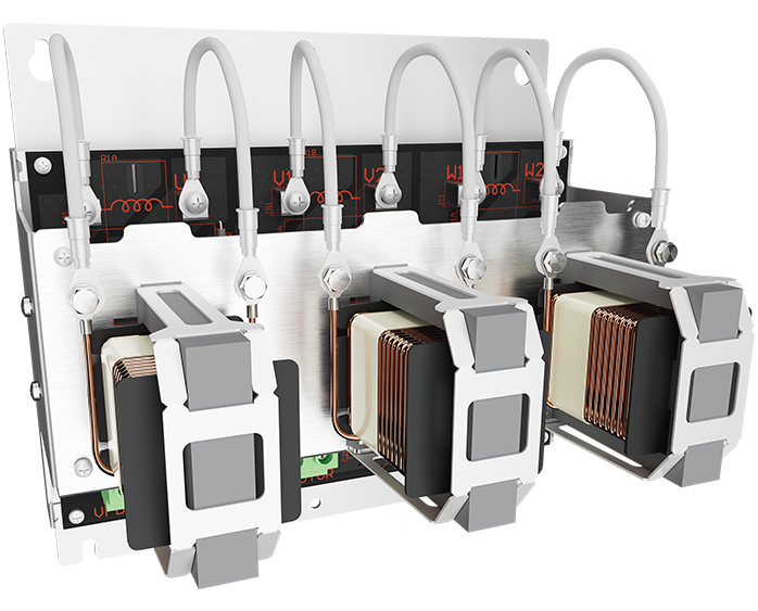
A motor protection filter is a device installed between a variable frequency drive (VFD) and an electric motor to reduce electrical stress caused by the VFD’s high-speed switching. It smooths out voltage spikes, minimizes electrical noise, and protects the motor’s insulation and components—ultimately extending motor life and improving system reliability.
Why use a dV/dt or Sine Wave Filter?
Protects motor insulation from voltage spikes and high dV/dt caused by VFD switching.
Reduces electrical noise and high-frequency harmonics on motor leads.
Extends motor lifespan by minimizing heat, vibration, and bearing stress.
Prevents reflected wave damage, especially in long cable runs.
Minimizes audible noise and electromagnetic interference (EMI).
Enables use of standard motors without requiring inverter-duty insulation (with sine wave filters).
Supports compliance with manufacturer recommendations and industry best practices.
dV/dt Filter
Purpose: Reduces the rate of voltage change (dV/dt) from the VFD output.
Waveform Output: Still a PWM (pulse-width modulated) waveform—just with less steep voltage edges.
Applications: Used for moderate motor lead lengths (typically 100–300 feet).
Protection Level: Helps prevent voltage spikes and insulation stress.
Sine Wave Filter
Purpose: Converts the VFD’s PWM output into a true sine wave.
Waveform Output: A clean, smooth sine wave, similar to utility power.
Applications: Ideal for long lead lengths (300+ feet), submersible pumps, or sensitive motor applications.
Protection Level: Provides near complete mitigation of voltage spikes, high-frequency harmonics, and common-mode currents.

