
Motor Protection - Quick Start Guide Installation
DV Series dV/dt and SW Series Sinewave Output Filters
QUICKSTART MP, Revision 000
Mounting the Output Filter
- If wall-mounted, loosen attached mounting brackets, rotate such that mounting hole extends above the chassis, and re-tighten.
- If floor-mounted, fasten legs using concrete anchors or similar.
- Intake and exhaust openings must not be obstructed. If mounted in an enclosed space temperature must remain below 40 C (104 F). Notes: 18" (450mm) clearance below and 12" (150mm) around required for ventilation.
Connect Wiring
Installation should be performed by a licensed electrician and comply with all applicable electrical codes.
- Ensure power is disconnected from the variable frequency drive (VFD).
- Remove front panel from output filter and route cables through supplied conduit openings in bottom of enclosure.
Note: Continuous metal conduit should be used for all power cables to reduce radiated electromagnetic interference (EMI). -

Install ground wires from both motor and VFD to the ground lugs provided in the filter enclosure.
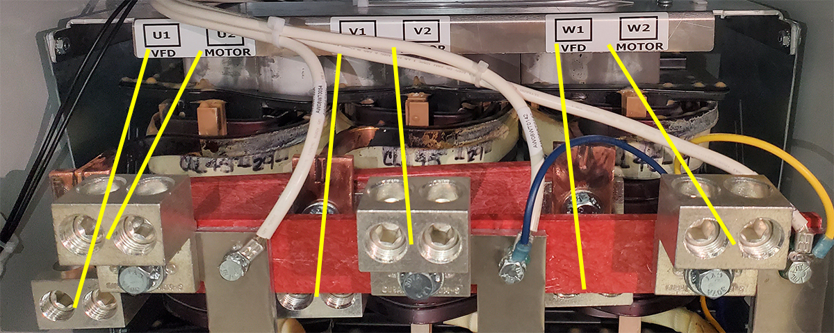
- Connect the motor power wires to the output of the filter (U2, V2, W2).

- Connect the output wires from the VFD to the input terminals of the output filter (U1, V1, W1).
WARNING!
Connecting wires improperly may result
in damage and will void warranty.
in damage and will void warranty.
Powering the Filter
- Re-install the front panel of the output filter.
- Ensure all VFD settings are compatible with the output filter and motor being used.
- Verify the Startup Checklist (see below).
- Reconnect power to and run the VFD.
Startup Checklist
- Filter is securely attached to the proper mounting surface.
- Filter ground terminals are properly bonded to earth ground.
- Filter input terminals are connected to the output of a VFD and the VFD is configured properly:
- VFD output frequency is less than 90 Hz.
- VFD PWM switching frequency is between 2 kHz and 8 kHz.
- VFD operation mode is Volts per Hertz without DC braking.
- Note: VFD motor auto-tuning procedures will be greatly affected and likely will result in inaccurate results. Consult with VFD supplier if auto-tuning is desired with filter installed.
- VFD, motor, and filter are ALL of an appropriate rating.
- Motor is connected to the filter output terminals.
- Motor is secured and properly mounted.
Download
Manual
phasetechnologies.com/support/mp
Manual
